Ethan
Combs

Mechanical engineer taking systems from concept through analysis, fabrication, and validated test data.

Education
B.S. Mechanical Engineering, Florida Polytechnic University
Graduating
December 2026
Seeking
Design, test, or product engineering
Based in
Lakeland, Florida

Capabilities

More than eight years in SolidWorks and six in Fusion 360, with simulation training in CFD and FEA.

Simulation and analysis

  • CFD in ANSYS Fluent
  • FEA in COMSOL Multiphysics
  • Stress–strain analysis
  • Vibrations and controls
  • PID tuning, root locus

Test and instrumentation

  • Tensile and compressive testing
  • Data acquisition
  • Optical encoders
  • IMU integration
  • Machine safety systems

Design and manufacturing

  • SolidWorks, Fusion 360
  • Design for manufacturing
  • Tolerance analysis
  • Custom PCB design in KiCad
  • FDM 3D printing, CAM

Embedded and controls

  • C, C++, Python, MATLAB
  • Arduino and ESP32 firmware
  • Actuator and servo control
  • Computer vision, ROS 2
  • CAN bus / OBD-II, Wi-Fi / IoT

Software and languages

  • SolidWorks
  • Fusion 360
  • Onshape
  • ANSYS Fluent
  • COMSOL Multiphysics
  • MATLAB
  • Excel
  • RStudio
  • KiCad
  • Arduino
  • ESP32
  • C
  • C++
  • Python
  • Visual Studio
  • GitHub
  • ROS 2
  • Bambu Studio
  • Creality Slicer

Certifications

  • Certified SolidWorks AssociateDassault Systèmes, 2020, renewed 2023
  • Fusion 360 Certified UserAutodesk, 2022
  • MATLAB CertificationMathWorks, 2024
  • Microsoft Excel Certification2024

Projects

Hardware I've designed, built, and tested, from load frames and gimbals to vehicle electronics and circuit boards.

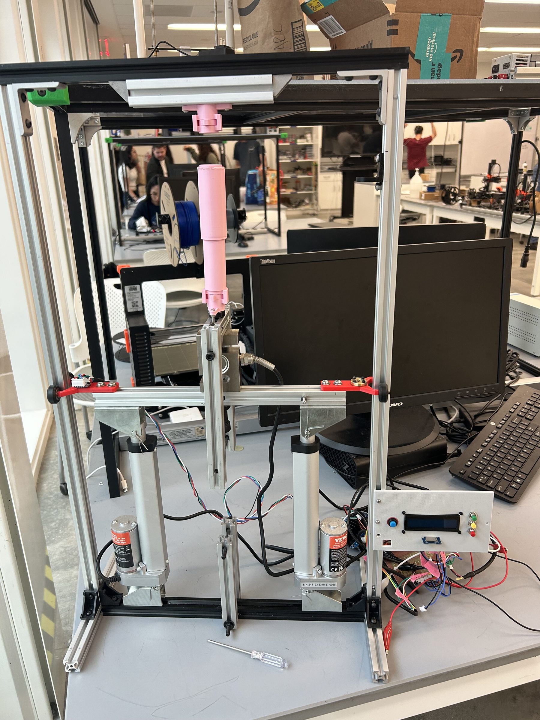
The test machine: aluminum extrusion frame, two linear actuators driving a crossbar, and the control box with an LCD

Load frame and control box

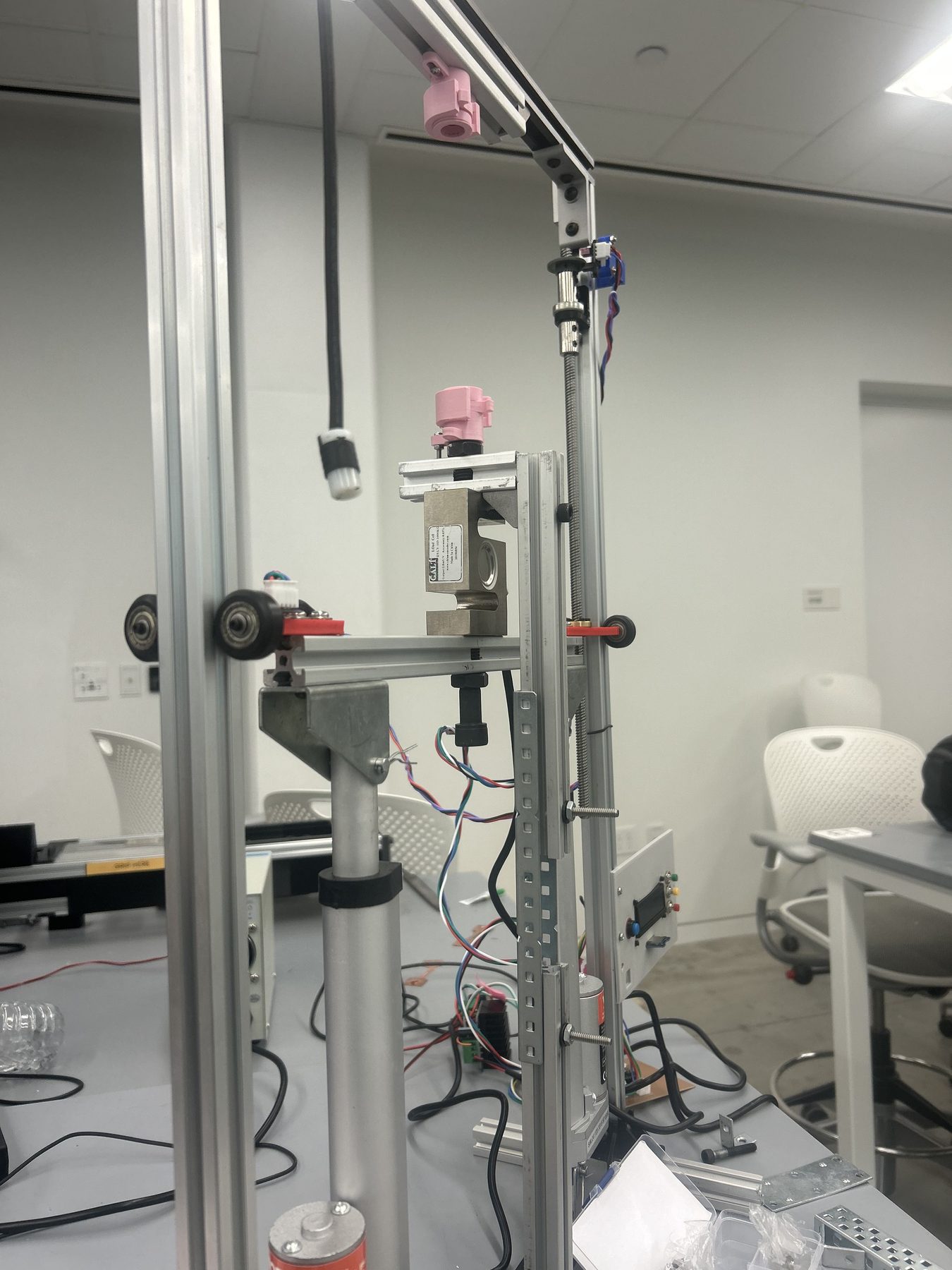
Close-up of the S-beam load cell mounted on the crossbar with 3D printed specimen grips

Load cell and specimen grip

Test and instrumentation

3,000 N tensile and compressive test machine

An industrial-grade materials test machine, designed and built on a student budget.

Two linear actuators drive a crossbar through an aluminum extrusion frame, loading the specimen in tension or compression. An S-beam load cell, an optical encoder, and an IMU feed an Arduino Nano on a custom PCB, and firmware I wrote turns the raw readings into engineering stress–strain curves.

Build details
  • Designed and built the machine to a 3,000 N rating in both tension and compression, integrating dual linear actuators, an optical encoder, an IMU, an Arduino Nano, and a custom PCB.
  • Developed the data acquisition and processing firmware that calculates engineering stress–strain curves at 97% accuracy.
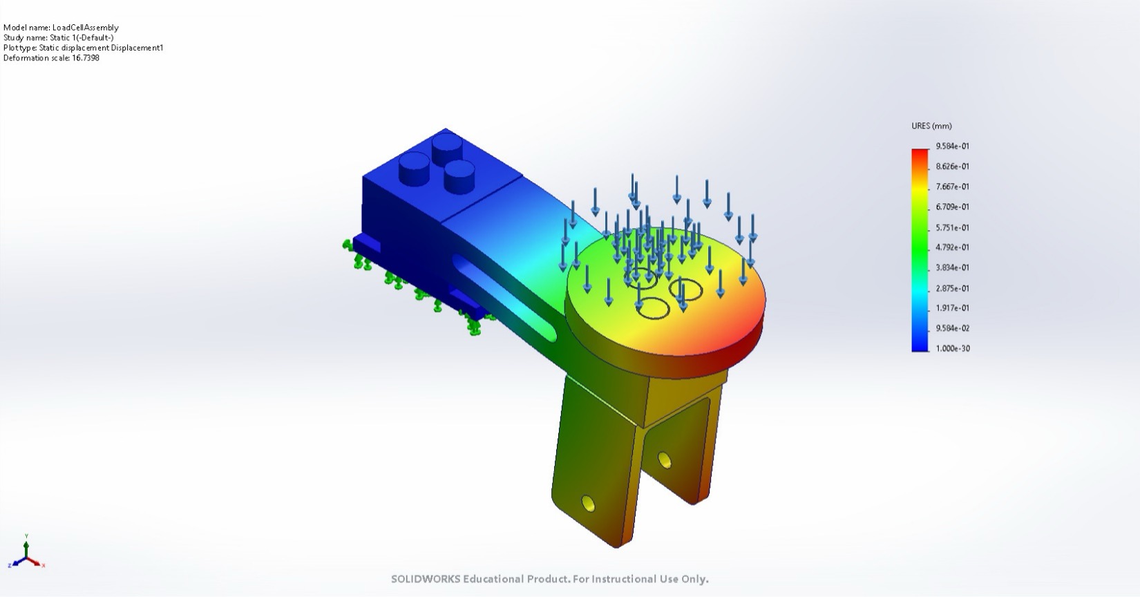
  • Checked the load cell mount with a SolidWorks static study before building it into the frame.
  • Designed the machine safety systems, including a shrapnel shield and emergency stops, to contain specimen failure.
Rated load
3,000 NTension and compression
Stress–strain accuracy
97%
Actuation
Dual linear actuators
Sensing
S-beam load cell, optical encoder, IMU
Electronics
Arduino Nano on a custom PCB, LCD control panel
Frame
Aluminum T-slot extrusion
Safety
Shrapnel shield, emergency stops
SolidWorks static displacement plot of the load cell assembly
Load cell mount, static FEA. SolidWorks displacement study of the load cell assembly. Peak resultant displacement is 0.96 mm, shown at 16.7× deformation scale.
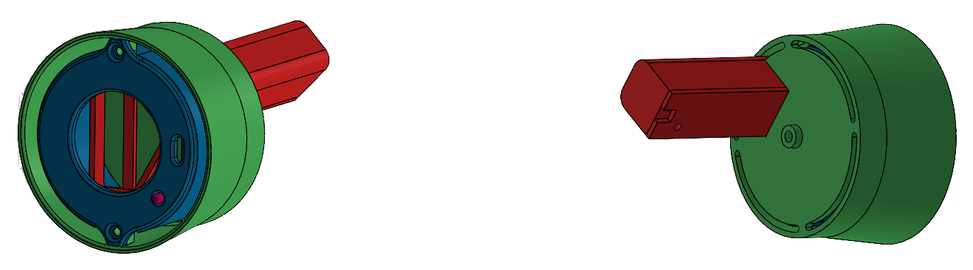
SolidWorks model of the vent-mounted gauge cluster enclosure, front and rear views

Enclosure CAD, front and rear

Automotive embedded systems

Digital gauge cluster for an Acura RSX

A battery-powered gauge cluster that lives inside a dashboard vent and reads the car's data live.

An ESP32 talks over Bluetooth to an ELM327 module, polling CAN bus and OBD-II data at high frequency and calculating acceleration on the fly. I designed the menu system, wrote the display firmware, and designed the enclosure in SolidWorks to fit the vent.

It runs on an 18650 battery, so power draw mattered: when the car reports zero speed and the data stream stops, the cluster puts itself to sleep.

Live data
RPM, coolant temperature, vehicle speed
Calculated
Acceleration, computed on the ESP32
Vehicle interface
CAN bus / OBD-II via Bluetooth ELM327
Controller
ESP32 with display firmware and a menu system I designed
Power
18650 lithium battery
Power saving
Sleeps when speed reads zero and the data stream stops
Mounting and enclosure
Inside a dashboard vent, enclosure designed in SolidWorks

Lane following

Full course run

Live detection feed

Autonomy

Autonomous vehicle with computer vision navigation

A four-wheel robot that drives itself around a scale city course, following lanes and reacting to what's in its path.

A forward camera feeds a Radxa ROCK 5C Lite, which handles lane following and runs an object detection model on its NPU. I trained that model myself on an RTX 2060 GPU before deploying it to the board. When the detector picks up an obstacle, the car stops or steers around it. The detections stream live to a browser dashboard, so I could watch what the car was seeing while it drove.

Navigation
Computer vision lane following
Perception
Object detection on the ROCK 5C Lite's NPU
Model training
Trained object detection model on RTX 2060 GPU
Obstacle response
Detects objects, then stops or steers around them
Monitoring
Live detection feed in a browser dashboard
Test course
Duckietown-style track with lane lines, stop lines, and tagged signs
Disciplines
Autonomous robotics, computer vision, mechatronics
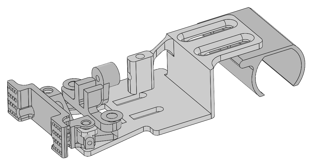
CAD model of the Hot Wheels car chassis with front steering linkage and rear mounting bracket

Chassis CAD

Wireless embedded systems

Wi-Fi controlled Hot Wheels car

A Hot Wheels car retrofitted to drive over Wi-Fi from a browser, a phone, or a sim racing setup.

I fit a dual-core ESP32 control board and a motor driver into the car and modeled the chassis in CAD to carry them. The ESP32 runs its own Wi-Fi stack, so any device on the local network can send it full directional control, from a browser tab to a sim racing rig.

Controller
Dual-core ESP32 with onboard Wi-Fi
Drive
Motor driver for full directional control
Control inputs
Browser, mobile interface, sim racing setup
Network
Local Wi-Fi network
Chassis
Modeled in CAD to package the electronics
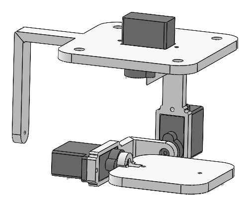
SolidWorks model of the three-servo camera gimbal

Gimbal assembly, SolidWorks

Controls

Three-axis gimbal stabilization system

A servo gimbal that holds an FPV drone camera steady, with gains placed by root locus instead of trial and error.

The gimbal rolls, pitches, and yaws to keep a 30 g FPV camera on target while the drone maneuvers. We modeled the gimbal arm and camera as a second-order plant, chose 5% overshoot and a 0.5 s settling time, placed the closed-loop poles in the s-plane, and solved for PD gains. A Seeed XIAO ESP32-C3 runs the controller.

Team project with Rebecca Moretta.

Design details
  • Modeled each axis as J·θ̈ + c·θ̇ = τ, using a 50 g, 80 mm arm and a 30 g camera at 70 mm for J = 0.000254 kg·m², with damping c = 0.002 N·m·s/rad.
  • The 5% overshoot and 0.5 s settling targets give ζ = 0.69 and dominant poles at s = −8 ± 8.39j.
  • Proportional control alone only reached ζ = 0.339, so we added derivative action and solved for Kp and Kd.
  • Wrote a MATLAB script for the step response and root locus, and checked the ESP32-C3's servo signal on an oscilloscope while it tracked a simulated sinusoidal drone sway.
Axes
3Roll, pitch, yaw
Overshoot
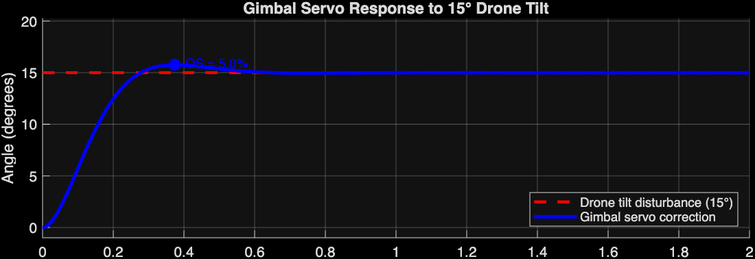
5.0%From a 15° tilt, MATLAB simulation
Settling time
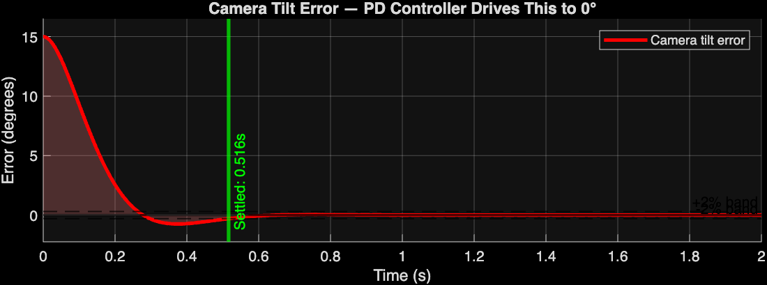
0.52 sWithin the 2% band
Plant model
G(s) = 3937 / s(s + 7.87)
PD gains
Kp = 0.0342, Kd = 0.00207
Hardware
Seeed XIAO ESP32-C3, MPU6050 IMU, three servos
MATLAB plot of the gimbal servo angle correcting a 15 degree drone tilt with 5 percent overshoot
Servo response to a 15° drone tilt. The correction peaks at 5.0% overshoot, matching the design target.
MATLAB plot of camera tilt error decaying to zero, settled at 0.516 seconds
Camera tilt error. The PD controller drives the error to zero and settles inside the 2% band at 0.516 s.
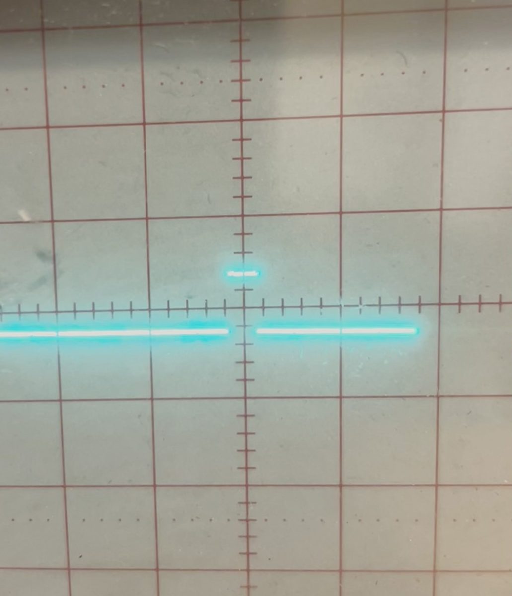
Oscilloscope screen showing the servo control pulse
Controller output on the bench. The XIAO ESP32-C3's servo pulse on an oscilloscope during the sinusoidal sway test.
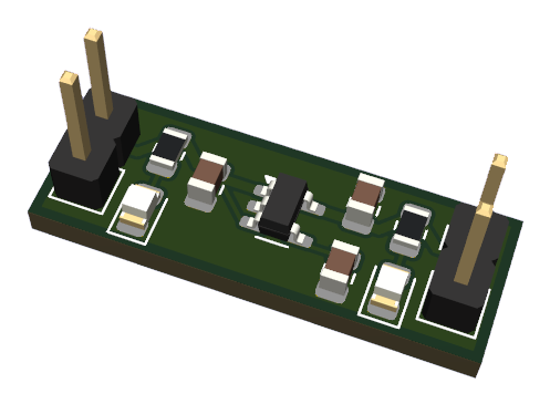
KiCad 3D render of the regulator board with input and output headers, SOT-23-5 regulator, capacitors, resistors, and LEDs

KiCad 3D render

PCB design

5 V to 3.3 V regulator board

A compact linear regulator board, designed in KiCad, that steps a 5 V supply down to a clean 3.3 V rail.

I drew the schematic, laid out the board, and checked the fit in KiCad's 3D viewer. A SOT-23-5 low-dropout regulator sits between input and output decoupling capacitors, with a bypass capacitor on its noise-reduction pin. An LED on each rail shows at a glance that 5 V is coming in and 3.3 V is going out.

Input
5 V2-pin header, J1
Output
3.3 V2-pin header, J2
Regulator
SOT-23-5 LDO, enable tied to input
Filtering
Input, output, and bypass capacitors
Indicators
Power LED with current-limiting resistor on each rail
Tools
KiCad schematic, PCB layout, 3D viewer
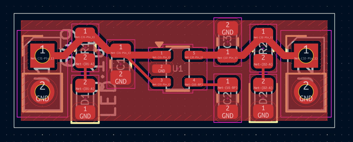
KiCad PCB layout of the regulator board showing J1, U1, J2, C1 to C3, R1, R2, D1, and D2
Board layout. Power enters at J1, passes through regulator U1, and leaves at J2. C1 and C3 decouple the input and output, C2 bypasses the regulator, and D1 and D2 light the 5 V and 3.3 V rails.

Heat transfer

Forced-convection comparison of copper heat sink fins

Four fin layouts, one forced-air cooling case, and a clear winner.

We compared zig-zag plate, cylindrical pin, curved plate, and rounded-rectangular fin arrays in copper, cooling from 80 °C in a 76 °F room under 22 mph (9.8 m/s) airflow. I designed the cylindrical pin and rounded-rectangular arrays, attempted to sand-cast the fins, and built an Arduino temperature-logging rig for physical tests.

When the casting stock turned out to be copper-plated steel rather than solid copper, the comparison moved to a Python model built on adiabatic-tip fin efficiency, the Churchill–Bernstein crossflow correlation, and lumped-capacitance transient cooling.

EML 4140 Heat Transfer, with Mitchell Parrish. Written up as an ASME-format report.

Predicted performance, copper, 22 mph forced air
Fin layoutInitial heat dissipatedTime to coolFin efficiency
Zig-zag plate52.8 W114.1 s93.8%
Cylindrical pin59.0 W36.9 s81.4%
Curved plate41.5 W92.5 s92.3%
Rounded rectangularBest238.9 W12.2 s89.6%

Time to cool is from 80 °C to within 1 °C of room temperature; shorter is better. The rounded-rectangular array is a 40 × 40 × 10 mm sink with 130 fins; the other three use 25 mm fins.

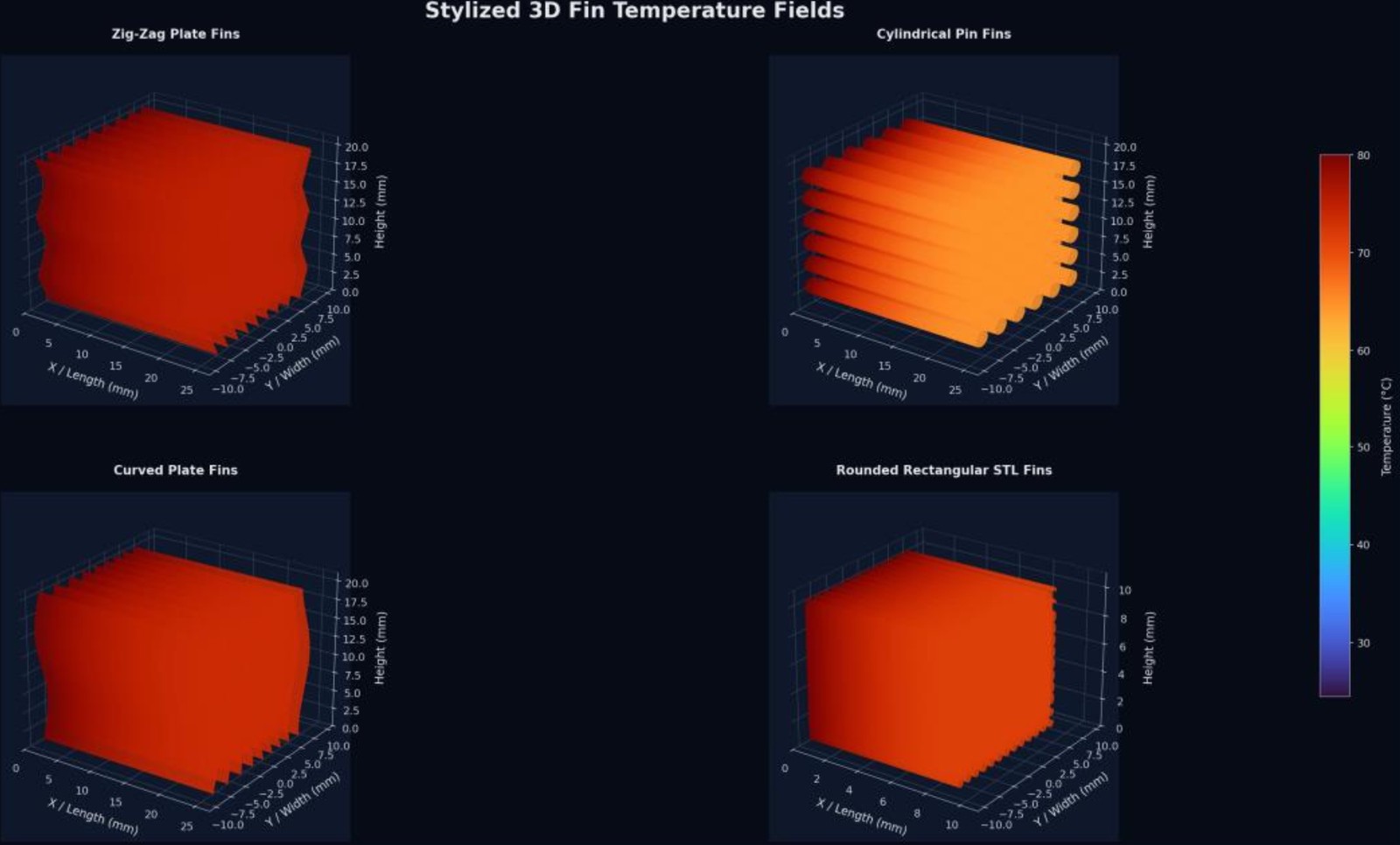
Stylized 3D temperature fields for the zig-zag plate, cylindrical pin, curved plate, and rounded rectangular fin arrays
Fin temperature fields. Modeled temperature across each of the four fin arrays at the start of cooling from 80 °C. The cylindrical pins show the steepest temperature drop along their length, since a round fin has more perimeter per unit of cross-sectional area.

Experience

Paid work where I owned the job from requirements to delivery.

2024 to 2025

Freelance CAD and additive manufacturing contractor

PEMB Construction Inc., remote

CAD model of the custom 'Cannibal by Brace Olds' vehicle emblem
Custom vehicle emblem, modeled for additive manufacturing.
  • Delivered contract CAD design and additive manufacturing for a pre-engineered metal building contractor, including a custom vehicle emblem taken from concept to production part.
  • Ran the full workflow independently: requirements, 3D modeling, print parameters, revisions, and delivery.
Jul to Aug 2022

Security installation technician

Self-employed, Lakeland, FL

  • Planned and installed a commercial security camera and alarm system, including conduit routing and network configuration of connected devices.

Also: property maintenance and operations assistant for a contractor services company, self-employed landscaper, and member of the Florida Polytechnic University volleyball team.

Hiring for design, test, or product engineering?

I'm available for full-time roles after I graduate in December 2026. The fastest way to reach me is email.